Two indexing tricks with PostgreSQL

I would like to share two indexing tricks I stumbled upon earlier this year. They are useful when changing the schema for large tables.

Context

Our database schema seemed rather inefficient:

  • We were using 8-byte bigint types for small integer keys, and 8-byte timestamp types for simple dates.
  • The columns were defined in a random order, with the resulting padding required to make the columns align (e.g. if the first two columns are a 4-byte integer and an 8-byte timestamp, the timestamp will need to be padded with 4 bytes of empty space so that it aligns to an 8-byte boundary). I was alerted to this padding cost by RhodiumToad on freenode’s #postgresql channel.
  • We used monthly partitions which made maintenance tasks, such as vacuuming and reindexing, effectively impossible.
  • We had indexes on both the primary key (which had 7 columns in it), and all columns used in foreign keys to help with referential integrity checks (e.g. when source_id on table forecast is a foreign key to table source, a delete or update on source needs to scan table forecast using source_id to check whether any of its rows are affected).
  • XML blobs were stored as plain text; at only 700 bytes each they were not large enough to be automatically compressed.

There is an obvious hazard of “premature optimisation” when addressing any of these. But when your data is 7 TB, your average partition size is 500 GB with another 500 GB of indexes, and it’s all running on incredibly slow NFS storage, it can be worth trying to do something.

(The database had earlier been migrated “as is” from Oracle, with the understanding that when it was working we could work on optimising it. I still wonder if we’d have found the migration less painful in terms of time and storage if we’d performed at least some optimisation of the schema beforehand.)

So that is what I eventually did — with a certain amount of proof-of-concept work in a separate, much, much smaller test database. This post is about the first point from the list above: inefficient column types and how to change them without rewriting all existing data.

Basic set up

Assuming the existing data is too unwieldy to convert to the new schema, we can create new tables with the new schema, and put a view in front of both the old and new tables to combine them into something the application can continue to work with.

In my case, the existing table looks like:

CREATE TABLE forecast (
    source_id BIGINT NOT NULL,
    validity_date TIMESTAMP WITHOUT TIME ZONE NOT NULL,
    ...
    PRIMARY KEY (source_id, validity_date, ...)
);

There are actually 13 columns on the table of various types, but these two columns are sufficient to illustrate the indexing tricks.

We will replace the forecast table with two tables and a view:

  • forecast_0 – formerly knows as forecast; the existing data in the old schema
  • forecast_1 – new data from this date on, in the new schema
  • forecast – a new view to be used in place of the old forecast table
ALTER TABLE forecast RENAME TO forecast_0;
CREATE TABLE forecast_1 (
    source_id INTEGER NOT NULL,
    validity_date DATE NOT NULL,
    ...,
    PRIMARY KEY (source_id, validity_date, ...)
);
CREATE VIEW forecast AS
SELECT source_id::integer, validity_date::date, ...
FROM forecast_0
UNION ALL
SELECT source_id, validity_date, ...
FROM forecast_1;
CREATE TRIGGER ...; /* various triggers for insert
    update,delete on forecast if needed by the app */

The new forecast view has the same column types as forecast_1 table. (In my case, the application will work with the new types without change.)

Querying

There is a now a huge problem. A typical query such as

SELECT * FROM forecast WHERE source_id = 101
AND validity_date = '2016-06-02';

is rewritten by the planner as

SELECT * FROM forecast_0 WHERE source_id::integer = 101
AND validity_date::date = '2016-06-02'
UNION ALL
SELECT * FROM forecast_1 WHERE source_id = 101
AND validity_date = '2016-06-02';

The criteria for the first subquery are on compound expressions such as source_id::integer and validity_date::date, which are not the simple column names source_id and `validity_date1 for which we have existing indexes. None of the indexes can be used and we get full table scans!

EXPLAIN SELECT * FROM forecast WHERE source_id = 42 and validity_date = '2016-06-02';
                                          QUERY PLAN
------------------------------------------------------------------------------------------------
 Append  (cost=0.00..2319239.47 rows=1215 width=423)
   ->  Seq Scan on forecast_0  (cost=0.00..2319233.42 rows=1214 width=423)
         Filter: (((source_id)::integer = 42) AND ((validity_date)::date = '2016-06-02'::date))
   ->  Index Scan using forecast_0_pkey on forecast_1  (cost=0.29..6.06 rows=1 width=82)
         Index Cond: ((source_id = 42) AND (validity_date = '2016-06-02'::date))
(5 rows)

This plan is from a small sample of one day’s worth of data and takes 15 minutes to run; in the full database it would take four days, which is problematic to say the least.

Trick 1: Create indexes for the new column types

If the expression being queried is source_id::integer, then an expression index on (source_id::integer), as another for (validity_date::date), could very well be the answer. Or, since both columns tend to be used in queries, a single index on (source_id::integer, validity_date::date).

CREATE INDEX ON forecast_0 ((source_id::integer), (validity_date::date));

This results in plan, using the new index, that brings the query time back to less than a second.

EXPLAIN SELECT * FROM forecast WHERE source_id = 42 and validity_date = '2016-06-02';
                                                    QUERY PLAN
-------------------------------------------------------------------------------------------------------------------
 Append  (cost=0.56..14.65 rows=2 width=252)
   ->  Index Scan using forecast_0_source_id_validity_date_idx on forecast_0  (cost=0.56..8.60 rows=1 width=423)
         Index Cond: (((source_id)::integer = 42) AND ((validity_date)::date = '2016-06-02'::date))
   ->  Index Scan using forecast_1_pkey on forecast_1  (cost=0.29..6.06 rows=1 width=82)
         Index Cond: ((source_id = 42) AND (validity_date = '2016-06-02'::date))

But there is a cost, in terms of time and storage space, of creating those indexes on the existing data. Instead, we can define the view forecast in terms of the old column types, and create the expression indexes on the new, empty tables:

CREATE VIEW forecast AS
SELECT source_id, validity_date, ... FROM forecast_0
UNION ALL
SELECT source_id::bigint, validity_date::date, ... FROM forecast_1;
CREATE INDEX ON forecast_1 ((source_id::bigint));
CREATE INDEX ON forecast_1 ((validity_dated::timestamp without time zone));

Of course, bigint indexes are bigger than integer indexes, so at some point down the road (perhaps when the old data has fallen out of the retention window and been discarded) it might be worth changing the view and the indexes to the new, more efficient types once and for all.

To make this easier when the time comes, the new tables can have indexes on the simple column names as well. When the view is rewritten in terms of the new types, the expression indexes created above will no longer be used and can be dropped.

Trick 2: Create mapping tables

What if we could tell PostgreSQL’s query planner that the index on bigint column “source_id” can be used for queries by source_id::integer?

We can, if we provide a way for it to map each integer source_id to its equivalent bigint value, and the same for the date/timestamp validity_date values. PostgreSQL is a relational database, and a lot of its smartness pertains to tables and the indexes on them. Let’s create some tables to contain the mappings for these two columns:

CREATE TABLE source_lookup
(
    source_id INTEGER,
    legacy_source_id BIGINT,
    PRIMARY KEY (source_id, legacy_source_id)
);
CREATE TABLE validity_lookup
(
    validity_date DATE,
    legacy_validity_date TIMESTAMP WITHOUT TIME ZONE,
    PRIMARY KEY (validity_date, legacy_validity_date)
);

We need to populate the mapping tables with every value that might be needed. Fortunately there are not that many of them. The source_ids can be found in the source table, and the validity_dates can be generated over a reasonable range covering all existing data:

INSERT INTO source_lookup SELECT source_id::integer, source_id from source;
INSERT INTO validity_lookup
SELECT d::date, d FROM generate_series('2015-01-01'::timestamp without time zone, '2017-01-01'::timestamp without time zone, '1 day') as s(d);

Now, we can recreate the forecast view using the mapping tables:

CREATE VIEW forecast AS
SELECT source_id, validity_date, ... FROM forecast_0
    JOIN source_lookup ON legacy_source_id = forecast_0.source_id
    JOIN validity_lookup ON legacy_validity_date = forecast_0.validity_date
UNION ALL
SELECT source_id, validity_date, ... FROM forecast_1;

How will PostgreSQL plan queries on this view? Note that source_id and validity_date in the view do not come from forecast_base_0; the come from the mapping tables, where they are the first columns of the primary keys. The secondary columns in those tables are then used to find the rows of forecast_base_0 needed to fill out the rest of the view.

EXPLAIN SELECT * FROM forecast WHERE source_id = 42 and validity_date = '20160602';
                                                        QUERY PLAN
---------------------------------------------------------------------------------------------------------------------------
 Append  (cost=2706.11..229455.53 rows=244 width=422)
   ->  Nested Loop  (cost=2706.11..229447.05 rows=243 width=423)
         ->  Index Only Scan using validity_lookup_pkey on validity_lookup vl  (cost=0.28..8.29 rows=1 width=12)
               Index Cond: (validity_date = '2016-06-02'::date)
         ->  Nested Loop  (cost=2705.83..228951.36 rows=48557 width=439)
               ->  Index Only Scan using source_lookup_pkey on source_lookup sl  (cost=0.28..8.29 rows=1 width=6)
                     Index Cond: (source_id = 42)
               ->  Bitmap Heap Scan on forecast_0  (cost=2705.56..228251.37 rows=69170 width=443)
                     Recheck Cond: ((source_id = sl.legacy_source_id) AND (validity_date = vl.legacy_validity_date))
                     ->  Bitmap Index Scan on forecast_0_pkey  (cost=0.00..2688.26 rows=69170 width=0)
                           Index Cond: ((source_id = sl.legacy_source_id) AND (validity_date = vl.legacy_validity_date))
   ->  Index Scan using forecast_1_pkey on forecast_1  (cost=0.29..6.06 rows=1 width=82)
         Index Cond: ((source_id = 42) AND (validity_date = '2016-06-02'::date))

Again, this results in a more efficient query that is able to use the existing indexes. Furthermore, it avoids the expensive step of creating expression indexes.

Posted in Programming | Tagged , | Leave a comment

One thing from 2014: a compiler and CPU working together

2014 was a sparse year for blogging and other projects. But at least some progress was made on my CPU project, including a major milestone: namely, running its first compiled program.

Stored-program computer

Firstly, the CPU is now capable of loading a program into instruction memory and then running it. Before now, the program had to be “hardcoded”; a situation not unlike that of early computers, which needed to be rewired to perform a different computation. The stored-program computer, which runs a program from memory, is a big thing in the history of computers.

Of course, one could simply have hardcoded a virtual machine program, and thenceforth have that VM run programs stored in data memory. (A primitive virtual machine is not too hard to write in assembly language.) But that would be ridiculous: an FPGA running a circuit that implements an instruction set in which a program is written that simulates a computer than runs programs in data memory.

At this point, the CPU had almost caught up with technology from 1948.

DEPP protocol

The main challenge for loading programs was IO. The FPGA has very simple IO devices. It looked like programs would need to be entered by setting the 8 switches to an 8-bit byte value, then pressing a button to enter that byte into memory. Repeat for the next 4095 bytes of the program. This option is do-able. More preferable is communication over a cable from another computer. Ethernet is one possible option, but implementing that, and then hardcoding a TCP/IP stack, might be a lifetime of work (and leave little room on the FPGA for a CPU and memory).

Another possibility is the USB cable connected to the host which powers the FPGA and uploads the circuit bitfile. The Digilent board provides something called DEPP (based on EPP, which is used for parallel ports). Several IO pins from the FPGA are assigned to DEPP, and software running on the host can send and retrieve data, if those pins have been connected to the appropriate circuitry. Implementing the DEPP circuitry was surprisingly easy with the help of online resources such as Hamsterworks (though I did have to learn VHDL to figure out what what going on there).

It felt good to see that first successful byte arrive from the host on the FPGA. Then another byte, and another. When I sent a test file of 100 bytes… 83 bytes arrived at the FPGA. Several days were spent rewriting the circuit, and copying and testing others’ circuits. Similar but different problems would occur with other people’s code: too many bytes, or bytes out of order, or junk bytes. I concluded there was inherent noise in the channel, and had resigned myself to designing an error-correction protocol, when I found out about metastability. Buffering two clock pins controlled by the host solved the problem (the problem being that while those pins were stabilising, they would be wavering up and down and each change would be interpreted as a data event).

The CPU can now be operated as follows:

  1. The FPGA is switched on and the circuit bitfile uploaded.
  2. The CPU is in “load” state. (This is displayed on the seven-segment disaply as LoAd — I have the beginnings of a 6-bit character set and really bad SSD font — you try making Ms and Ws out of the seven segments!)
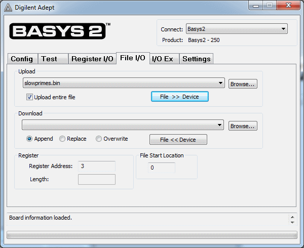
  3. The host sets the DEPP address to 3 (designated as “upload instruction byte”), and sends bytes of program data.
  4. The host writes 1 (“reset”) to DEPP address 0 (“state”).
  5. The CPU performs a reset and begins executing the program from memory.
  6. Later, the host sets the CPU back to “load” (byte 0 to address 0), sets the instruction load address to 0 (byte 0 to address 2), and sends a new program before again setting the CPU state to “reset”.

I have seen consoles from some computers from around 1960, and I believe they worked like this.

Data memory and IO devices

Late in the year I finally figured out data memory, using Xilinx block RAM primitives. I had earlier spent a lot of time puzzling over it, wondering why words sometimes could not be read out after being written. I gave up and put it aside for a few months. On resuming the work I found my problems were caused by a bug in instruction decoding, where the register numbers for value and address were not taken from the proper parts of the instruction. This a classic example of the hazard of implementing functionality before it can be tested. The code in question is simple, and I wrote it envisioning how data memory would work, but without it being run and the data memory verified as working, a simple error in the code was not picked up until much later.

The CPU’s IO system was also refactored. The FPGAs switches, buttons and LEDs can be controlled using the IN and OUT instructions. The SSD also has a few new modes. It can display a word (or two) of data as decimal, hexadecimal, or alphanumeric. As mentioned above, there is a simple character set (where the digits and alphabet occupy the first 36 character positions — this is very convenient for performing base conversion, e.g. when displaying a value in hexadecimal).

One unresolved issue in the CPU design is the relationship between CPU ports (which a program can use to control th IO devices), and the control ports, such as the CPU state and the instruction memory upload ports. I have an urge to unify them, partly to make the assignments of ports easier to remember, but mostly to enable the host to control IO, and also to allow the CPU to control its own internal state — e.g. a program could alter instruction memory or reboot the CPU by writing to the appropriate ports. The only real hurdle is that DEPP is based on bytes, but the CPU (and its IN/OUT instructions) work with 16-bit words. Always writing byte-pairs over DEPP would be annoying, as would restricting IO addresses and values to 8 bits.

First compiled program

And finally, I have made some progress on the accompanying compiler. A few weeks ago I was able to take this test program:

//#include <stdio.h>

void main() {
    int max;
    max = 10000;
    
    int candidate;
    candidate = 2;
    
    while (candidate < max) {
        int divisor;
        divisor = 2;
        
        while (divisor < candidate) {
            int multiple;
            multiple = 0;
            while (multiple < candidate) {
                multiple = multiple + divisor;
            }
            if (multiple == candidate) {
                break;
            }        
            divisor = divisor + 1;
        }
        
        if (candidate == divisor) {
            __out__(candidate, 18);
            //printf("%d\n", candidate);
        }
        
        candidate = candidate + 1;
    }
}

And compile it:

$ ./compiler.py slowprimes.e > slowprimes.asm
$ cat slowprimes.asm
main::
    mov 10000, $r8
    mov 2, $r9
L25:
    slt $r9, $r8, $r7
    br $r7, L7
    jmp main$exit
L7:
    mov 2, $r5
L31:
    slt $r5, $r9, $r3
    br $r3, L11
L28:
    sub $r9, $r5, $r1
    br $r1, L26
L27:
    mov 18, $r4
    out $r9, $r4
L26:
    mov 1, $r2
    add $r9, $r2, $r9
    jmp L25
L11:
    mov 0, $r11
L32:
    slt $r11, $r9, $r10
    br $r10, L15
L29:
    sub $r11, $r9, $r12
    br $r12, L30
    jmp L28
L15:
    add $r11, $r5, $r11
    jmp L32
L30:
    mov 1, $r6
    add $r5, $r6, $r5
    jmp L31
main$exit::

And assemble it:

$ ./asm.py slowprimes.asm -b > slowprimes.bin

And upload it to instruction memory:

slowprimes1

And run it:

slowprimes2

Of course, it did not actually run first time. This was not due to a bug in the compiler, or the assembler, or the CPU. It was due to a bug in the test program. (As you can see, there is now a commented-out call to C’s printf — I could have treated it as C and compiled it gcc and had it correct long before implementing the compiler!)

It did run second time, though. This was very satisfying.

Posted in Hardware, Programming | Tagged , , | Leave a comment

Hiatus

Over a year has passed since I posted anything here.

What’s been happening? I have changed job. I’m not overworked by any means, but I have found that I have less time and energy left for the frivolous, but stimulating, pursuits that inhabit this blog. This was not intentional, but it is not easy to climb back into the habit of regular writing once fallen out of it.

Some things I could have written about:

  • Making a very simple assembler for my CPU.
  • Beginning yet another overly-ambitious compiler project, for compiling simple programs into input for the aforementioned assembler. (Yet again, I’m stuck on register allocation!)
  • A VGA driver and a few demonstration graphics circuits (Verilog programs; I know we’re supposed to call them IP Cores but I can’t get past the fact that the legal concept of “intellectual property” has nothing to do with computer science or electronics: circuits it remains!) including some bouncing balls and a Mandelbrot fractal. The output image quality is poor because the FPGA lacks a good timing crystal. The Mandelbrot is low resolution because the FPGA has only a few kB of memory.
  • A raytraced reconstruction of the Antikythera mechanism.
  • Learning about climate science, heterogeneous parallel programming, combinatorial game theory and image processing in some online courses.
  • Finally getting a Raspberry Pi! It has a surprisingly high fun/cost ratio.
  • Teaching myself some Erlang. I really enjoy the mental sensation of learning a new style of programming, but I have not found a suitable project I can apply Erlang to. I am playing with Nitrogen with the aim to write a simple web app for playing videos, which runs on my Pi — on port 31416, naturally. The incumbent state-of-the-art method for playing a video is to ssh into the Pi from my iPad, and enter a omxplayer command to play a movie file located in a mounted directory.
  • Writing a program for generating Penrose tilings. For no particular reason, initially, but it does make a nice pattern to print on a Pi case (that’s a prototype).
  • Sundry rants about life, the universe and everything.

Now all I have to do is pick one of those projects and actually finish it, and then I’ll have something to blog about.

Posted in Hardware, Programming, Reflections, Science | Tagged , , | Leave a comment

A computing machine

As mentioned previously, I’ve been trying my hand at Verilog — a language for designing electronic circuits. This post discusses the next project I attempted: a Central Processing Unit.

Magic of computation

A CPU is the part of a computer that coordinates all the other parts of it. It reads the program from memory, determines what each instruction of the program means, and reads, writes or otherwise manipulates memory, disk, screen, and other devices according to each simple instruction. CPUs are where the magic of computation happens. And computation is magic; the only magic that exists in the real world: the special kind of magic that is indistinguishable from sufficiently advanced technology.

It is easy to take for granted that a small device bought from a shop can display text or images from remote locations. But general purpose computers are marvellous machines that were unknown to humanity for thousands of years. The realisation that physical machines can manipulate intangible data has a history from the Antikythera mechanism to Babbage’s Analytical Engine. All these machines were special purpose (though the Analytical Engine was Turing complete). A general computer can be programmed to mimic any one of these, and an infinite variety more.

Modern CPUs are massively complicated and contain millions of individual design parts. The driving force behind this complexity is not the discovery of new kinds of computation; it is the demand for speed. Faster computers do permit new applications. However, even a slow, simple, primitive computer such as the one described here can execute the same algorithms as any more sophisticated computer.

Motivation, inception and development

Computer hardware, especially CPUs, is mysterious to most of us. Most people, even most programmers, are happy for it to remain so.

I was introduced to logic gates at school. There was no real computer science curriculum in those days, so what kind of exposure you got to computer science was a combination of your own study and your fortune in having a proactive teacher who knew something beyond how to use a word processor. My teacher was Martyn Leda who knew lots of things besides word processing. One of the classes was “Computer Programming” which introduced us to a plethora of languages and included some low level things like assembly programming, and some circuit design. I think it was after learning about turning gates into half adders into full adders and so on that I began to whimsically “design” my first CPU. The combinational logic was obvious, and I knew something about flip flops, but everything about how the CPU actually got work done was obscured by liberally applied handwaving.

It was also the case that my inspiration was the Intel 8086, a CISC design. Those chips were designed for an era and purpose in which hardware was expensive and programming effort was relatively cheap. Consequently, they were far from simple designs and featured many complications to make the most of hardware. (Later chips are more complicated still, internally: they support the original 8086 instruction set and its successors, but they do so by emulating those chips on top of a completely different lower level computer design.)

Years later at university I took a class on hardware, based on the textbook Computer Organisation by Patterson and Hennessy. This book covers a large part of computing hardware design, including a description of a complete MIPS processor from its logic gates to its assembly language. That book gave me one of those rare learning experiences in which a curtain is drawn back, and the hitherto mysterious system behind it is revealed. The system is still as marvellous as before. Now there is also wonder at how it was created, and moreover, that it can be comprehended by people like me.

That course was completely theoretical. It was not until I began learning Verilog that the few missing parts of my mental CPU design began to drop into place and I had a realistic chance of seeing it work. Kris (who got me started with Verilog) suggested (perhaps jokingly) that I should make a “4 bit CPU”.

The actual design was different, and inspired not only by the 8086, and by MIPS, but also by Charles Thacker’s Tiny Computer 3. A short PDF describes this computer and even contains 2 pages of Verilog code. My CPU turns out to be quite different and far less concise, efficient and capable.

I’ve put the Verilog source on Github. The README file there includes a description of the architecture. At the end of this post I’ll list some of the outstanding limitations and outline some possible next steps.

Over a few days I created the basic CPU, testing it in Icarus. It took as much work again to get it running on an FPGA! A number of changes had to be made:

  • Unsynthesisable constructs: these were mostly $display and some of ways values were initialised. The worst was my use of $readmemh to load the program memory. This should be synthesisable but Xilinx had so much trouble I ended up copying and pasting the hex values from my program into the Verilog source.
  • An outer layer for FPGA use. The CPU is useless and arguably meaningless if it can’t communicate with the real world. In simulation, it can print to the console. On an FPGA, it cannot do that, so it needs to communicate using the device’s IO capabilities, such as the seven segment display.
  • Timing issues: in many places I’d relied on the simulator’s use of an event queue to perform simulation updates in a useful order. In the real world, updates are applied simultaneously, so on the FPGA nothing was happening in the order I expected. (Verilog does allow timing directives to make the simulation reflect real world conditions, but I have not mastered these.)
  • More timing issues: in many places I’ve derived new clock signals using combinational logic. This doesn’t work so well in the real world. Arguably it’s because there will be so much more skew with the derived signals. More practically in my case, it’s because the synthesis tools cannot analyse the derived clocks and hence have no idea what the timing constraints on them are. I could run my CPU on the FPGA by stepping down the clock rate by a factor of a million — there was some Verilog code that would count the ticks of the FPGA’s source clock at 50MHz, and update a derived CPU clock whenever the count reached a certain number. As I reduced the slowdown and the CPU ran faster, eventually it would start computing garbage. The solution was to replace derived clocks with the use of a single source clock, and enable signals. That signal clock is described in the constraints file, and the synthesiser can recognise all the circuits that depend on it and ensure the paths through them are shorter than 50MHz.

Machine in action

Often a new computer or virtual machine is demonstrated by running a port of Quake or other well known program on it. Sadly, such feats were well beyond my CPU’s capabilities at the time I first got it running in hardware (a few weeks after beginning to learn Verilog).

This video shows the CPU in operation, computing the Fibonacci sequence. The display is in hex. This does make the output somewhat strange, but it a lot easier for a binary computer to generate. (Circuitry to turn a binary number into a sequence of decimal digits for display is not trivial!)

Here is the source for that Fibonacci program. This is not assembly language — there is no assembler for this machine yet. This is hand typed machine code. True, I did not have to enter it one bit at a time by toggling a switch. Compared to programmers of yesteryear I was blessed with a text editor to type it in, a hexadecimal based code format, and a very simple instruction set.

0000 // FIBONACCI EXAMPLE
E300 // Set Limit = 32768
F380 // "
E701 // Set Increment = 1
F700 // "
E600 // Set Counter = 0
F600 // "
E100 // Main loop: Set A = 0
F100 // "
E201 // Set B = 1
F200 // "
B001 // Fibonacci loop: Output 0 to port 1
B201 // Output B to port 1
3432 // Check if Limit < B
D405 // If so, exit loop
0512 // Set C = A + B
0102 // Set A = B
0205 // Set B = C
C0F9 // Jump to Fibonacci loop
0667 // Increment Counter
B600 // Output Counter to port 0
C0F2 // Jump to Main loop

Each 4-digit number is an instruction. The first digit is the instruction, for instance 0 is add. The next three digits are the register numbers to operate on, or constant values to use. Line 16 means “add the values from registers 1 and 2 and store the result in register 5”. The most difficult instruction to write was the jump COF2 on line 22. C is jump; but the offset is made from the last two digits and addresses are modulo 256. Jumping by F2 = 242 is the same as jumping by -14. The effect is to move the instruction pointer back to line 8.

Where next?

Although the instruction set contains load and store instructions, the CPU has no actual data memory! Many interesting things can be computed using a handful of registers, but I admit that I’m not sure I can port Quake to it without some support for arrays.

Additionally, the CPU cannot manipulate program memory, save for executing it. It can’t be read, it can’t be written, and it can’t even be addressed properly. The instruction pointer is hidden and all jumps are relative. This is a consequence of the design: the instruction format provides only 4 bits for the opcode, yielding a maximum of 16 instructions. Even when additional instructions are easily implemented, it is hard to find distinct opcodes for them.

I believe that arrays and function pointers, at least, will need to be supported for the CPU to be capable of supporting C programs. Writeable memory is also a requirement for proper general purpose use: instead of reading a hardcoded program memory, the CPU should boot up, read the program from somewhere, and start running it.

The instruction format is constricted but there is a nascent “ports” system that provides expandability. There is no standard assignment, but on the FPGA I’ve wired some ports to the seven segment display. Others could be wired to other devices. Similarly, the memory address space could be partitioned into program memory, data memory, and video memory.

As shown above, the instruction set is relatively easy to program by hand. But an assembler would make it easier. A compiler would be even better!

It should be noted it is far easier to muse on these possible improvements than it is to go forth and implement them. The CPU project is primarily for learning and amusement. When motivation depends on amusement it is easy to slack off once all the really interesting bits have been done. But some other FPGA-related projects have suggested a use for a small microprocessor core. Even with HDLs like Verilog, there are still many algorithms that are easier to implement as programs than as circuits.

Posted in Hardware, Programming | Tagged , , | 1 Comment

Learning Verilog

Over my summer break I learned Verilog. Verilog is a hardware description language: it’s a kind of programming language in which, instead of providing a sequence of instructions for updating a computer’s state, or composing an expression that evaluates a function for some input, we specify how digital components are connected to each other.

For instance, the canonical 8-bit counter tutorial is:

module counter(output [7 : 0] out, input clk, input reset);

    /* Increment or reset the counter when clk goes high. */

    reg [7 : 0] out;
    wire clk, reset;

    always @(posedge clk)
        if (reset) begin
            out <= 0;
        end begin
            out <= out + 1;
        end
        $display('counter is now %d', out);
endmodule

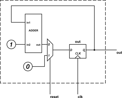
This can be simulated directly, or synthesised into a digital circuit; an abstract version might be:

circuit

(I’ve not settled on the most efficient way to draw circuit diagrams. This one was drawn with CircuitLab).

Simulation entails updating each part of the imaginary circuit when its input changes. Verilog provides certain “unsynthesisable” processes, such as $display, which have meaning in simulations. The one on line 14 of this program prints the new value of out to the console every time it is updated.

Verilog is hence a very simple, cheap and effective way to design, test, and refine circuits, without needing to warm up the soldering iron. I use Icarus Verilog for simulation. It does not simulate the electronic physics but will still demonstrate the behaviour of the circuit and will pick up a large class of possible design errors.

Very basic HDL technique

Programming with digital components requires different techniques from normal imperative or functional programming. Unlike imperative programming, there is no flow control. And unlike functional programming, there is no laziness. Every part of the circuit is continuously being updated based on its inputs. Effects from those parts of the circuit that are not needed are masked out.

Verilog can describe many kinds of circuit, but as I am still a novice I restrict myself to an easily-understood subset. This limited but practical way of constructing a digital circuit is to treat it as a simple function from states and input, to states. A clock ticks at a regular interval, and on each tick the state is updated based on that function. The function must be so simple that the longest path through it can be electronically evaluated within a single clock period. This generally means no loops.

An algorithm is stated in terms of that function. Here is an example, my first original Verilog program.

module gcd(output [WIDTH-1 : 0] acc, output [WIDTH-1 : 0] out, output ready,
        input [WIDTH-1 : 0] in1, input [WIDTH-1 : 0] in2, input clk, input reset);

    /* GCD module.
     *
     * Set in1, in2 to the inputs, then set reset high momentarily.
     * Pulse clk repeatedly.
     * When ready is high, out will contain the GCD.
     * acc and out are updated as the algorithm progresses.
     */

    parameter WIDTH = 8;

    reg [WIDTH-1 : 0] acc, out;
    reg ready;
    wire [WIDTH-1 : 0] in1, in2;
    wire clk, reset;

    always @(posedge clk)
        if (reset) begin
            acc <= in1;
            out <= in2;
            ready <= 0;
        end else if (!ready) begin
            if (acc == 0) begin
                ready <= 1;
            end else if (acc < out) begin
                acc <= out;
                out <= acc;
            end else begin
                acc <= acc - out;
            end
        end
endmodule

On each tick of the clock signal clk, there are four possible computations that can be performed, depending on the current values of reset, ready, acc and out. The abstract circuit this corresponds to has components that continuously compute the four possible new states, as well as components to decide which of those computed states is chosen as the new values of the registers ready, acc, and out. When the clock ticks, the new state is loaded into those registers.

Moving onto actual hardware

Circuits can easily be simulated in software, and in the age of Verilog they often start out that way. Simulations are fun and affordable, and it is easy to develop and analyse a digital circuit in the abstract. But circuits live most naturally in hardware. Some people have the knowledge, tools, and manual dexterity to wire transisters onto a circuit board. But for the rest of us, there are Field Programmable Gate Arrays!

An FPGA consists of a large number of logic components — adders, lookup tables, registers, wires — which can be “programmed” to behave like any of a significant subset of digital circuits. Programming is done by uploading a bit pattern which describes exactly which components in the FPGA are actually needed for the circuit and how they are connected.

One introductory FPGA development board is the BASYS 2. (One of which was acquired by Kris for his own Verilog developments, and kindly loaned to me for the weekend.) This consists of a Xilinx Spartan 3 FPGA, some programmable ROM to carry the bit pattern for it, and a number of easily accessed IO devices. The Xilinx IDE is flabbergastingly complicated; almost impressive in its intimidating and confusing layout. But it was a surprisingly simple matter to synthesise a bit pattern from a Verilog file. This is then transferred to the board and activated:

It’s counting seconds. In hex.

Something more challenging

A $200 piece of hardware laboriously programmed using an arcane language to count seconds in a non-human-friendly number system is, of course, impressive in its own right. But the digital circuit that most readily springs to a programmer’s mind is one that can be configured to perform arbitrary computations, i.e. a CPU. This was the aim of my second Verilog project.

Posted in Hardware, Programming | Tagged , | 2 Comments

IRC bot as a fun project

Something I started working on last year: yet another IRC bot.

Since IRC is a simple protocol for sending plain text messages to channels or users, it provides opportunities for some good programming projects, such as a bot. An IRC bot is something that connects to an IRC network and provides some kind of automated service to the users on it. The potential applications of a bot are endless, and the only real limitation is that it has to communicate via plain text.

Writing an IRC bot is an excellent project for an interactive program — within a few days you can have something that runs on the network and responds to messages. If you have an idea for something useful or fun it can do, even better. You just need to program the bot to understand for some commands and behave appropriately.

Probot

My previous IRC bot was called Probot, and was written in C and Prolog: C to do all the low-level networking stuff, and Prolog to provide dynamic and configurable behaviour.  The implementation was a C program that used SWI-Prolog’s C library bindings.

The idea was that it would receive commands in IRC messages in the form of Prolog goals, and it would then print the results of solving those goals. For example:

<edmund> probot: X is 2 +2 .
<probot> X = 4.

Or, with a slightly more ambitious goal involving access to outside data, backtracking and output:

<edmund> probot: pb_get_nicks(Ns), member(X, Ns), format(atom(G), 'Hi, ~s!', X), pb_speak(G).
<probot> Hi, ChanServ!
<probot> Hi, edmund!
<probot> Hi, probot!

pb_get_nicks/1 and pb_speak/1 are predicates which return the IRC nicks of the currently visible users, and send a message to the IRC channel. The rest is standard Prolog: non-deterministically pick a member X of Ns, construct a greeting G, and send it to the channel, then backtrack until all possibilities are exhausted.

Of course, some predicates in Prolog change the environment. So it was possible to send commands to the bot that would affect how it processed further commands.

<edmund> probot: assertz(hi :- (pb_speaker(X), format(atom(G), 'Hi, ~s!', X), pb_speak(G))).
<edmund> probot: hi.
<probot> Hi, edmund!

The entire Prolog program is a database of rules, which can be manipulated on the fly. Of course, Prolog is not the most straightforward language to use for this purpose. But I had envisioned various hooks and shorthands that would make this easier, for instance, defining goals that should be solved on each kind of IRC event. The syntax could be improved by defining new Prolog keywords, and even Prolog’s Definite Clause Grammars could be used to add domain-specific languages for certain tasks. Sadly, envisaging is as far as I got with it before I lost the source.

xBot

Last year there was a discussion on IRC about bot programming, spurred by the creation of xBot. xBot is a modular bot written by Milos Ivanovic that provides a variety of services to an IRC channel. One of the clever things about xBot as a Python program, is that the services are defined in modules, and modules can be loaded and changed without restarting the bot. This makes the develop-test cycle for bot services much, much shorter.

Starting again: IRCbot

We were comparing notes and I was reminiscing about Probot to anyone who would listen. Since it’s such an approachable project, I undertook to repeat it. The new bot would be more general purpose and not based on an esoteric logic programming language. Python is a good language to use for general projects of this sort (and it means I can borrow the reload functionality from xBot).

But what should IRCbot do? Choosing an original and suitable name for the project had sorely taxed my imagination. Coming up with realistic and useful features for it was no easier. The typical IRC bot responds to a formal command language, or simply makes announcements from an external source.

A more challenging (and interesting, but admittedly, less likely to be useful!) approach is to respond to IRC conversations in natural languages. There are several examples of conversation bots, such as the famous ELIZA and the more modern Cleverbot (which xbot has a module for). A long time ago I was interested in the Loebner Prize, which is awarded each year to the program which comes closest to passing the Turing Test. I had ideas back then on analysing natural language, but I have learned a lot since; partly through studying formal languages in computer science, and partly through taking a stronger interest in language. I am not an linguist by any means but I think a program I wrote now would process language in more interesting ways than what I was planning back then.

A possible role of IRCbot is to connect a source of natural language — conversations on IRC — to a natural language analyser. Quite what the point is, I have not yet decided. But it will be interesting to see how sentence structure can be recognised, and how repeatedly used words relate to each other over the course of a conversation. This is still a long way from being a viable Loebner Prize entry (which would require the program to uphold one end of a conversation), but may give interesting results, and should be an interesting programming challenge in any case (which is what I’m really after).

IRCbot therefore provides two avenues of exploration: construction a reasonable IRC bot architecture, and the creation of a natural language processing engine. I will blog about these in the future.

Posted in Programming | Tagged , , , | Leave a comment

Cluster size experiment

After getting the SSD for my system, I’ve been able to repartition the existing HDD into a data-only drive. I typically have a small partition for general files (basically my documents and source code), and a big one for large files (various media).

The question was: what cluster size should I choose for each partition?

Received wisdom

In the past I choose the default size of 4 kB for most partitions, with a larger size for those on which I know I’m going to be storing large files. This habit was formed out of received “wisdom” (i.e. peer pressure) and a general understanding of file systems. The practical effects of these choices are, as I understand them, roughly the following:

    • 4 kB – the default NTFS cluster size, which enables useful features like compression. Compression should not generally be used but can be extremely useful when you have large quantities of compressible data that you need to keep available but which is infrequently used. Writing to compressed files can be expensive, but for reading they can be even cheaper than uncompressed files, because fewer disk reads are necessary for the same amount of data. The tradeoff depends on whether disk bandwidth or CPU time is the more precious commodity in your system.
    • 4 kB – matches the memory page size (which could conceivably make paging marginally more efficient, but I honestly have no evidence of that and insufficient knowledge to do more than list it as a possibility).
    • 4 kB – has modest internal fragmentation, with an average of 2 kB wasted per file. (The smallest cluster size of 512 bytes has even less fragmentation, of course. But it may have other downsides.)
    • 64 kB – ensures a large minimum extent size, so at least 64 kB can always be read contiguously.
    • 64 kB – has potentially high internal fragmentation — average of 32 kB wasted per file. With large files this will be negligible, but for small files the amount of wasted space will be significant.
    • 64 kB – there will be fewer clusters in the partition, so less file system metadata may be required. My understanding is that NTFS uses extents to record cluster usage, but some things such as free space bitmaps may be smaller.

Normally I’d be satisfied that these are adequate choices, and resigned to the fact that I probably won’t notice any difference.

But this time, I thought I’d put a bit more research into the decision. Not only did I want to make the new system as efficient as possible, I was also curious about whether my HDD partitioning beliefs these past years were accurate.

What advice does the internet have? As expected, a lot. Some of it is based on rather suspect reasoning, and all of it seems to be on assumption rather than experience — let alone experimental data. There were no obvious benchmarks to be found. Perhaps it was time someone conducted an experiment.

Expectations from basic theory

Without knowing much about file systems, it is reasonable to guess that, in addition to the cost of reading or writing data, there is an overhead per cluster accessed.  So, the fewer clusters to be accessed per unit size, the lower this overhead will be.  The number of clusters is inversely proportional to the cluster size.  The total cost of cluster accesses becomes significant when there are very many small clusters in a file.

Another possibility is that with larger clusters, there will be a larger amount of excess data in any cluster that is accessed.  (Although it’s possible that NTFS optimises partial cluster reads and writes down to their minimal size in blocks.)  So, when accessing a full file there is an average of half a cluster of unused data in the final cluster to be read or written; similarly when reading or writing at any point within a file, an entire cluster must be accessed.  This cost is proportional to the cluster size, and so becomes great when cluster sizes are very large.

The sum of these costs for cluster size s is A/s + Bs for some constants A and B.  The shape of this curve in general is a very high peak where the first term dominates for small s, dipping as s increases, and then climbing again as the second term dominates.  This suggests that for any given task, there is an optimum cluster size somewhere between the two extremes (but note that all permitted cluster sizes may be reasonable in practice).

The experiment

For each cluster size between 512 bytes and 64 kB, perform a benchmark:

      1. Start with a partition on the HDD.
      2. Format it with the candidate cluster size.
      3. Make a note of the free space on it.
      4. Benchmark for moderate sized files:
        1. Copy a large data set of files from another location.
        2. Make a note of the space remaining after the copy.
        3. Randomly read from a location in each file.
        4. Read the full contents of each file.
      5. Benchmark for large sized files, using the same steps as for moderate sized files.

Avoid performing any other activity on the computer while benchmarking. Repeat each benchmark several times to average out these effects.

The drive to be tested is a Western Digital Caviar Green 2TB, with 64MB Cache running on SATA II. The same partition is reused, which takes up the last 67% of the drive. (A common danger of benchmarks in the past was the use of different parts of a drive for each test — such as comparing Windows vs Linux file system performance on a machine with a partition for each operating system; the speed of the drive can depend on which part of it is being accessed.)

The same data sets of files are used in each benchmark. The moderate sized file set consists of 30,497 files of total size 11.2 GB. The large sized file set consists of 134 files of total size 20.4 GB. The same pattern of random reads is used in each benchmark.

Results

I have conducted the above experiment and I’ll try to summarise the results here.

Space usage

Firstly, some observations on space usage.  The initial space after formatting the partition depends on the cluster size.  In fact, approximately 8 bytes of space is required per additional cluster.

And, as expected, larger cluster sizes result in some wasted space in the final cluster of each file (internal fragmentation).  For small files on large clusters this can be significant.  For sufficiently large files we expect to waste half a cluster per file.  But if many files are smaller than half a cluster then more will be wasted.  For my set of moderate size files, the average waste for clusters of size 64kB was 42.5kB (on an average file size of 387kB).

Speed

Very small clusters are noticeably inefficient for simple copying.  For both small and large files, cluster sizes of 4096 or greater are all approximately equal in performance.  Note that the “small files” of this experiment were not especially small; the small cluster sizes may have more favourable performance when the files are closer to that size.

For random reads, the results are less obvious.  There is some penalty for small clusters, but there is also very poor performance for the large cluster size of 32kB.  For both big and moderate files, the best cluster size for random reads is the largest, 64kB.  This goes against the expectation that large clusters have an additional cost incurred by the waste of accessing a whole cluster when only part of it is used.

For full sequential reads of all file data, we have the interesting phenomenon that moderate sized files benefit more from large cluster sizes than do large files.  I’m not sure how to explain this; it may be due to the small sample size.  The effect is too small to conclude that cluster size makes much difference for this task.

Conclusions

For all tasks tested, cluster sizes smaller than the default — those that are 512, 1024 or 2048 bytes — are less efficient than the default size of 4kB.  As mentioned, those sizes may still pay off if very small files are to be stored on the file system.

Above the default size, larger cluster sizes confer benefit for some tasks, even for moderately sized files that may occupy only a few clusters each.

The largest cluster size of 64kB can result in 10% more space being used for the moderate sized files used in this test.

The speed differences seen in this test between the large sizes and the default size were not significant enough to recommend large sizes.  But a future experiment with more benchmark samples, larger test sets, and better experimental conditions may give clearer data.

I was curious to see whether there are obvious benefits to large cluster sizes.  Apparently, there are not.

Posted in Hardware, Programming | Tagged , , | 28 Comments

More thoughts on version control

The shadow of Git has lately begun to loom over my programming habits. It has actually become the principal version control system at work, with most active projects migrated to it from ClearCase, Mercurial, CVS, etc. And recent collaborative programming work on my own projects (such as on the Python analysis program) have made me realise that using a distributed source control system from day one can pay off if and when someone wants to fork your work.

I have been an extremely loyal Subversion user for almost ten years — I started using it in November 2002. Not only has it been my main source control system for all my personal projects, documents, and general data, but it’s been a satisfying outlet for some of my own version control related endeavours:

  1. A few small patches I’ve contributed to the Subversion project.
  2. One of the first attempts at an SQL storage backend.
  3. A full text repository indexing tool and database.
  4. A web-based repository browser, like ViewVC or Github (lost!).
  5. A general repository rewriting program (for retroactively fixing metadata and file contents (also lost!).
  6. A revision replay script, which has actually been useful for copying changes from The Ur-Quan Masters to Project 6014.

Even now, the Subversion command line and the TortoiseSVN GUI for Windows are the easiest to use, most robust, and best supported version control tools I know of. I believe they were the right choice for Project 6014, even with distributed alternatives, because all of those alternatives are harder to set up, require much more understanding to use (commit vs push, pull vs fetch vs checkout), and frankly, stlll don’t have the UI support. These are still important requirements, because not everyone who could benefit from version control is going to be a skilled programmer. For 90% of version control activity, Subversion just works.

Unfortunately, Subversion has the inherent limitation of centralisation. This is actually more of a problem for me as an individual user than it would be for a large corporation. I like to program both on my home computer and my netbook, and without constant network connectivity there is no way to have full source control on each. The Subversion repository would be hosted on one (the desktop computer), with a checked out working copy on the other (the netbook). Using my netbook away from home, I would be unable to view the history of the files, and unable to check in changes. I would have to wait until I had a network connection. The worst part of that is that when I made many separate changes to the source during the day, they would be checked in all once, or carefully managed by hand as temporary files to be checked in individually. That kind of tedious manual work and potential for error undermines the point of having version control.

The centralised Subversion model is still useful for a closed organisation with a good network, and its portability, simple command line, and well-polished GUIs should make it appealing to a corporate environment with users of many skill levels. Unfortunately for Subversion it scored badly against several alternatives. This was somewhat unfair as it was incorrectly deemed to fail on several requirements, but there are admittedly other weaknesses. It is somewhat inefficient, and it creates bloated and inconvenient metadata directories throughout the working copy.

And it isn’t distributed, and merging is very primitive (and prone to error, when you try to do something complicated). (But from what I have seen these are unlikely to matter in our organisation.) So, Git it was. And admittedly Git is the best out of the alternatives. It’s fast (in some circumstances; as I type this I’m importing 5000 files into a new repository at a rate of 1 per second). And it’s distributed (if you need that, and it’s better to have it available if you do). And it’s the way of the future.

Unfortunately, Git is much more complicated. It is more powerful (which excuses some of the complexity), but it also has accidental complexity and has not had its interface optimised for simple, everyday use — the way Subversion has. We also use Github at work. I sometimes wonder if it’s because people didn’t realise Git and Github were different things. It has proved to be a rather flaky web-based repository interface, with a confusing layout and too much focus on flashy features like dynamic page changing animations. It is good to have a centralised location of our organisation’s source code (hey, it almost sounds like we’re reinventing centralised version control…), and a web-based interface is the best general browsing mechanism for it. But we should remember that Git doesn’t imply Github (or vice-versa), and ensure that we can continue to use version control without needing to go via the centralised location.

It is important to note that I’ve used Subversion for almost a decade. I am still learning Git, having only used it for some PostgreSQL hacking (implementing loose index scans) a couple of years ago (before the fire; I still have the code but it got messed up when PostgreSQL formally moved their code base to Git, and my clone of an experimental Git repository was no longer compatible with the new official one). And recently I’m been adopting it at work. So my assessment of its usability needs to be tempered by an acknowledgement of my inexperience with it. It’s obvious, though, that Git will become the most popular version control system from now, and it will only get more polished and supported.

What seems to be a suboptimal choice for a corporate environment can have features that are ideal for personal use. The public Github site has free hosting (for open source), features like wikis and issue tracking, and some interesting graphs.  Mmy favourite is the punch card:

Tuesday seems to be the best time for fractals!

And as advertised, it’s “social”. One can fork a repository and be have that relationship tracked. So it’s great when an open source project you want to hack on is hosted there, and you can fork it to get your own copy to work on. There are a few projects I’d like to fork and work on, which will be easier with Git (even those that aren’t hosted on Github). And occasionally someone might want to fork one of mine. I would like to save them having to create an isolated copy; with a fork we can exchange improvements as each side continues development.

Furthermore, it’s often said that “a Github account” is necessary for an impressive portfolio. No one says the same of “a Google Code account” but that’s the power of marketing for you. Of course, it won’t make an practical difference, but having put all that effort into those programs, I would appreciate some improved visibility for them. You never know what someone else might find useful.

Github has a more personal system with a page for each user, and subpages for their repositories; this will be change from the Google Code system of monolithic project pages, and gives me a change to separate my projects out into separate repositories.

So I’ve created a new acccount at Github and, with some some trepidation, I’ll be moving my code into it. I’m not sure how it will work out so I’ll be taking some time to learn how to best use it and evaluate its effect on my project productivity…


Posted in Programming, Rants | Tagged , , , | Leave a comment

Programmer-friendly blogging

Commenting on a blog post about an interesting use of generics in Java, I’ve had the pleasure of seeing my carefully typed code translated from:

public Connection<Closed> close(Connection<Open> c) ....

Connection<Closed> c2 = close(c);

to:

public Connection close(Connection c) ....

Connection c2 = close(c);

Gosh, I never realised type erasure could be performed at the HTML level. Unfortunately this almost completely impaired my comment, in full view of the public. (It can be reconstructed with a bit of common sense, but you have to have the generosity to assume the writer would not intentionally write such spurious junk, which may be too much to ask of the online community :p.)

Writing about programming using standard blogging software is not generally as painful as it once was. WordPress, for instance, provides a sourcecode shortcode, which enables code for many languages to be safely pasted into a post and reliably formatted (but unfortunately not XML-based code, which is subject to being reescaped every time it is viewed in the editor, culminating in a bloated mess like &amp;lt;data x=&amp;quot;42&amp;quot;/&amp;lt;). So there are many blogs with nicely presented source code samples.

Commenting remains programmer-unfriendly. Comment boxes often support plain text, with a limited set of HTML elements (for bold, italics, linking). And as witnessed in today’s example, those elements that aren’t supported can be stripped out rather than treated as intentional text input. And the other problem with comments is they can’t be edited, so the author does not know how their unsupported text wil be rendered until it is too late to use a workaround.

This addition to my experience as a blog writer and commenter makes me feel that HTML is no longer the state of the art for simple, human- (and programmer-) friendly text markup. Humans want something that:

  1. Supports common typesetting features like bold, italics, lists, and links.
  2. Is easy to type, with few unusual symbols and no need to worry about proper nesting in simple cases.
  3. Is readable when being written as markup (an approximation of its rendered form).

And programmers desire these features too, as well as:

  1. Allows source code to be pasted in and rendered attractively, without requiring the code’s various symbols to be escaped lest they trigger some other behaviour on the input system.

Markdown seems to be the way to go. Github supports it, and Gists are increasingly being used as blog posts (though the Github interface is awful). StackOverflow supports it for answers, where it provides a live preview of the rendered result.

As mentioned when I first started blogging here, I think it would be great if WordPress supported Markdown — for posts and comments. It would be great if other platforms, such as the Blogspot site where I attempted to post my comment, followed suit, so that it became the de facto standard for text input on the internet. I do think even normal humans would find themselves using it as a straightforward, efficient, and reliable middle ground between the misfocus of WYSIWYG and the unfriendliness of HTML.

PS. Hmm, my code examples got type-erased when I wrote this post, too…

Posted in Programming, Rants | Tagged , , | Leave a comment

Schema diagrams for PostgreSQL

I have made some progress towards the longstanding goal of drawing nice diagrams of database schemas. Firstly, I’ve figured out how to use yEd‘s Entity Relationship node types as table nodes. These special node types have both a node label, and an additional content field. The additional field is normally free text but can also contain HTML data (akin to GraphViz‘s support for HTML nodes).

So a database table can be drawn with its name in the label, and a list of fields in the node body. And, with HTML mode, that list can be a table with columns for name, type, PK/FK status, etc.

But yEd has not quite caught up with GraphViz. In GraphViz, cells in an HTML table can be identified with ports, and an edge drawn between nodes can then target specific ports in each. yEd only supports a handful of predefined ports per shape (the centre, each side, and each corner). Furthermore, its automatic layout algorithms ignore the port data, and draw edges to the nearest part of a node. Still, those layout algorithms are the great strength of yEd and flexibility vs layout is a reasonable tradeoff.

Since entering the HTML contents by hand is time-consuming and prone to error, I’ve written a quick program to do it. The program, pgschemagraph.py, is run against a live PostgreSQL database. It will examine the table and foreign key definitions in the given schemas, and generate a GraphML representation of them.

Here is an example, taken from my “filesys” database:

Schema for the “filesys” database, generated by pgschemagraph.py.

The complete steps to create this diagram are:

  1. pgschemagraph.py -h localhost -d filesys -u edmund -p ***** -s public > filesys-schema.graphml
  2. Open filesys-schema.graphml in yEd.
  3. Run Orthogonal Layout with default settings (Alt-Shift-O, Enter).

As you can see, pgschemagraph.py has found the tables, their fields and types (including standard SQL types, user defined types like “cube”, and domains like “imageid”), the primary keys (indicated by underscoring) and whether they can be NULL (indicated by italics). It has also discovered the foreign key relations between tables.

Because the program works in terms of abstract database definitions, rather than nicely drawn diagrams, it does not do much layout. When first loaded in yEd, this file will show the tables stacked atop one another. The most pgschemagraph.py can do is guess the height of each node based on the number of rows in it (based on a heuristic of 22 points per line in the default font; it can’t do the width, because it does not know how wide each character is).

But it does perform about 80% of the work required to draw a good diagram. A human can easily and quickly do the rest.

At present it uses the standard information_schema catalog rather than the PostgreSQL-specific pg_catalog. The aim was that this would make it easier to port to other systems that support information_schema. The downsides are that information_schema is actually slightly difficult to use (since it’s very generic), and does not provide some useful information such as inheritence and partition relationships. In some of my schemas, tables are partitioned into multiple subtables. It would be nice to that represented in the diagram, rather than have the subtables floating around unconnected. So a rewrite to use pg_catalog may be in order. (Porting to alternative systems will then require a more system-specific approach).

More information can always be shown on the diagram. One idea is to allow different colours to be used. This could be done by schema, or by grouping of tables.

It would be possible to have the program run yEd’s layout engine directly.  Sadly, yEd is proprietary software, and however much I appreciate its help in laying out my diagrams, I’m averse to depending on it directly.  Generating the standard GraphML output (and potentially .dot output, for GraphViz), and running the program myself is a reasonable compromise.

The program, pgpgschemagraph.py, is on Github.

Posted in Programming | Tagged , , , , | 7 Comments