Over my summer break I learned Verilog. Verilog is a hardware description language: it’s a kind of programming language in which, instead of providing a sequence of instructions for updating a computer’s state, or composing an expression that evaluates a function for some input, we specify how digital components are connected to each other.
For instance, the canonical 8-bit counter tutorial is:
module counter(output [7 : 0] out, input clk, input reset);

    /* Increment or reset the counter when clk goes high. */

    reg [7 : 0] out;
    wire clk, reset;

    always @(posedge clk)
        if (reset) begin
            out <= 0;
        end begin
            out <= out + 1;
        end
        $display('counter is now %d', out);
endmodule
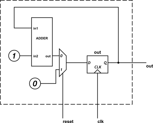
This can be simulated directly, or synthesised into a digital circuit; an abstract version might be:
(I’ve not settled on the most efficient way to draw circuit diagrams. This one was drawn with CircuitLab).
Simulation entails updating each part of the imaginary circuit when its input changes. Verilog provides certain “unsynthesisable” processes, such as $display, which have meaning in simulations. The one on line 14 of this program prints the new value of out to the console every time it is updated.
Verilog is hence a very simple, cheap and effective way to design, test, and refine circuits, without needing to warm up the soldering iron. I use Icarus Verilog for simulation. It does not simulate the electronic physics but will still demonstrate the behaviour of the circuit and will pick up a large class of possible design errors.
Very basic HDL technique
Programming with digital components requires different techniques from normal imperative or functional programming. Unlike imperative programming, there is no flow control. And unlike functional programming, there is no laziness. Every part of the circuit is continuously being updated based on its inputs. Effects from those parts of the circuit that are not needed are masked out.
Verilog can describe many kinds of circuit, but as I am still a novice I restrict myself to an easily-understood subset. This limited but practical way of constructing a digital circuit is to treat it as a simple function from states and input, to states. A clock ticks at a regular interval, and on each tick the state is updated based on that function. The function must be so simple that the longest path through it can be electronically evaluated within a single clock period. This generally means no loops.
An algorithm is stated in terms of that function. Here is an example, my first original Verilog program.
module gcd(output [WIDTH-1 : 0] acc, output [WIDTH-1 : 0] out, output ready,
        input [WIDTH-1 : 0] in1, input [WIDTH-1 : 0] in2, input clk, input reset);

    /* GCD module.
     *
     * Set in1, in2 to the inputs, then set reset high momentarily.
     * Pulse clk repeatedly.
     * When ready is high, out will contain the GCD.
     * acc and out are updated as the algorithm progresses.
     */

    parameter WIDTH = 8;

    reg [WIDTH-1 : 0] acc, out;
    reg ready;
    wire [WIDTH-1 : 0] in1, in2;
    wire clk, reset;

    always @(posedge clk)
        if (reset) begin
            acc <= in1;
            out <= in2;
            ready <= 0;
        end else if (!ready) begin
            if (acc == 0) begin
                ready <= 1;
            end else if (acc < out) begin
                acc <= out;
                out <= acc;
            end else begin
                acc <= acc - out;
            end
        end
endmodule
On each tick of the clock signal clk, there are four possible computations that can be performed, depending on the current values of reset, ready, acc and out. The abstract circuit this corresponds to has components that continuously compute the four possible new states, as well as components to decide which of those computed states is chosen as the new values of the registers ready, acc, and out. When the clock ticks, the new state is loaded into those registers.
Moving onto actual hardware
Circuits can easily be simulated in software, and in the age of Verilog they often start out that way. Simulations are fun and affordable, and it is easy to develop and analyse a digital circuit in the abstract. But circuits live most naturally in hardware. Some people have the knowledge, tools, and manual dexterity to wire transisters onto a circuit board. But for the rest of us, there are Field Programmable Gate Arrays!
An FPGA consists of a large number of logic components — adders, lookup tables, registers, wires — which can be “programmed” to behave like any of a significant subset of digital circuits. Programming is done by uploading a bit pattern which describes exactly which components in the FPGA are actually needed for the circuit and how they are connected.
One introductory FPGA development board is the BASYS 2. (One of which was acquired by Kris for his own Verilog developments, and kindly loaned to me for the weekend.) This consists of a Xilinx Spartan 3 FPGA, some programmable ROM to carry the bit pattern for it, and a number of easily accessed IO devices. The Xilinx IDE is flabbergastingly complicated; almost impressive in its intimidating and confusing layout. But it was a surprisingly simple matter to synthesise a bit pattern from a Verilog file. This is then transferred to the board and activated:
It’s counting seconds. In hex.
Something more challenging
A $200 piece of hardware laboriously programmed using an arcane language to count seconds in a non-human-friendly number system is, of course, impressive in its own right. But the digital circuit that most readily springs to a programmer’s mind is one that can be configured to perform arbitrary computations, i.e. a CPU. This was the aim of my second Verilog project.


Very interesting – are you gonna elaborate a little more at some point on your CPU?
Pingback: A computing machine | EJRH